
Kit for beginners.
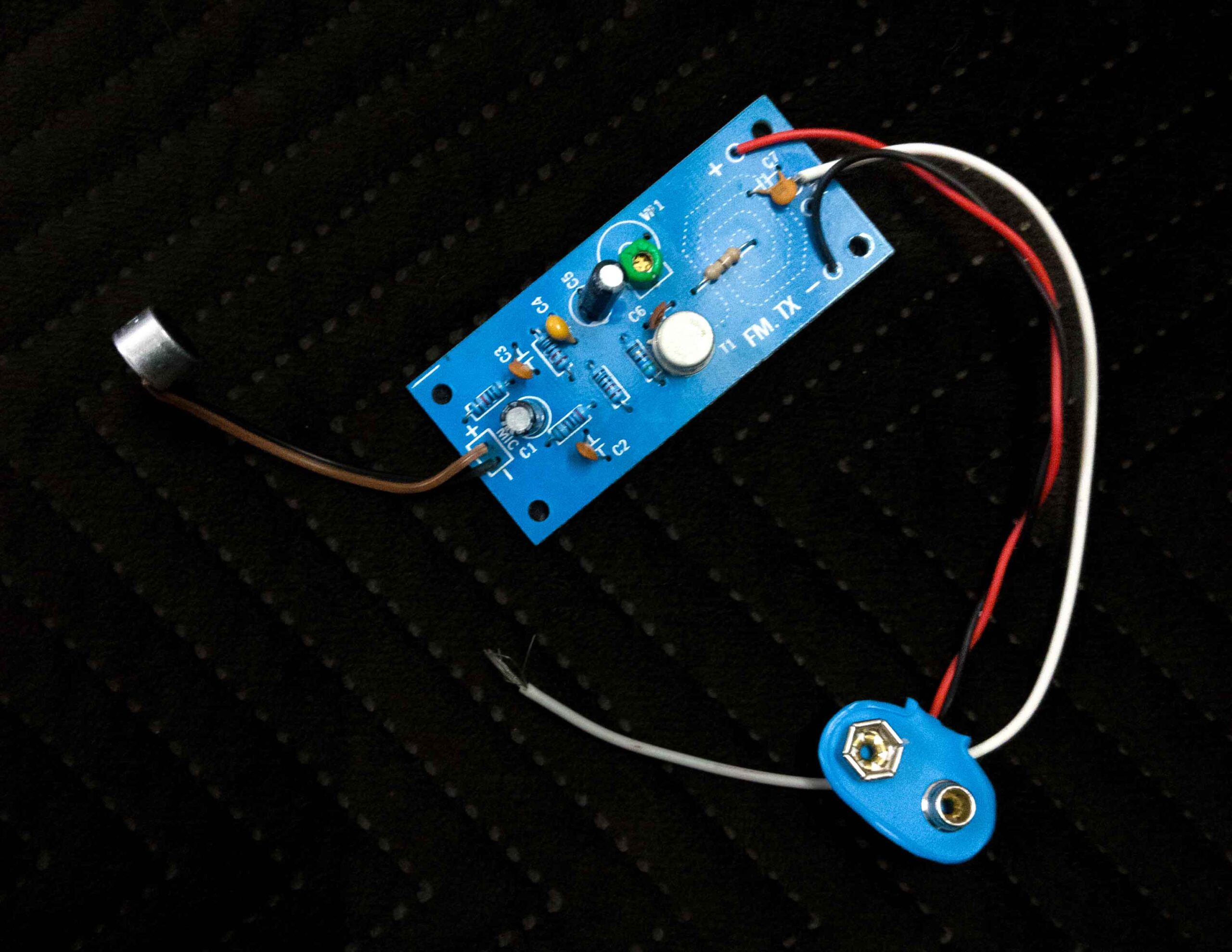
This is a single transistor FM Transmitter using RF Medium Power Transistor.
The circuit oscillates at 88 – 108 MHz FM Broadcast Band.
Microphone Signals are driven through the Transistor for amplifying the signal and directly fed into oscillator for modulation.
By adjusting the Green Trimmer frequency can be varied. The circuit uses Track Inductor as oscillator coil. Use 75 cm wire (λ/4) as antenna for best result.
Use 9V Battery to power the Transmitter. Test the Mini FM Transmitter after soldering the components using the RF Detector (to be assembled before assembling the Transmitter). Keep the RF Detector Coil near the Track Inductor. If RF is generated the LED will glow. Adjust the Green Trimmer to vary frequency 88 -108 MHz.
For long distance transmission use Dipole or Yagi Antenna etc. The length of each pole is 75 cm (λ/4) and use 75 Ω co-axial cable.
Component List:
PCB – Printed Circuit Board
T1 – 2N4427 or Equivalent
VC1 – 18 pF trimmer
R1, R3, R4 – 10 KΩ
R2 – 2.7 KΩ
R5 – 56 Ω
C1, C5 – 10 µF electrolytic
C2, C3 – 470 pF disc
C4 – 0.01 µF (103) disc
C6 – 4.7 pF
Condenser Microphone
9V Battery