
This is the first step into the world of RF (Radio Frequency).
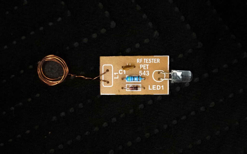
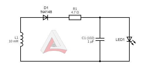
The circuit uses a sensing coil to detect RF energy and the signal is passed through the Detector Diode and fed directly into the LED without any amplification. The RF Signal generates the electricity by electromagnetism in the coil which powers the circuit and the LED glows.
By using this LED RF Detector also known as RF Tester, we can detect RF Generation. Just keep the Sensing coil (L1) near Track Inductor of the transmitter, if it generates VHF Signals, the LED will glow.
Component List:
1. Printed Circuit Board (PCB).
2. L1 – Sensing Coil
3. D1 – Detector Diode 1N4148 or Equivalent.
4. R1 – 4.7 Ω or 10 Ω.
5. C1 – 1 µF disc (102).
6. LED1 – Light Emitting Diode.